First Output!
Controlling the Full Display
The previous test with simple PWM demonstrated the rudiments of a control signal for the LED’s, but all we could do is spam 1’s or 0’s continuously. For real control, we need to vary the PWM duration every cycle to change whether or not to send 1’s or 0’s.
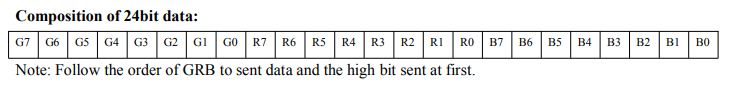
Let’s take a simple example: we have only three pixels connected in series. We want to show one red, one green, and one blue in that order. The control frames for the WS2812 LED’s are 24 bits of data, representing one byte (0-255) green, one of red, and one of blue:
So to make our green, red, blue pattern, we need to send the following control values:
LED 1: 255, 0, 0
LED 2: 0, 255, 0
LED 3: 0, 0, 255
Or, written as a continuous buffer of bytes:
255, 0, 0, 0, 255, 0, 0, 0, 255
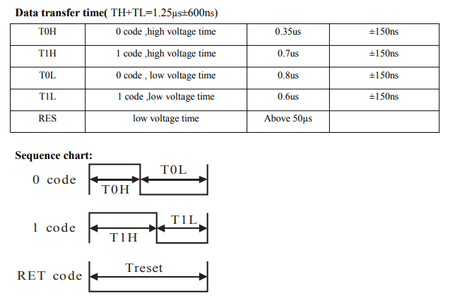
So nine bytes, consisting of 72 bits. Each bit takes 1.25μs to send. A 1 is a long high pulse followed by a short low pulse. A 0 is a short high pulse followed by a long low pulse. The sequence terminates to 50μs or more of low signal:
Then the procedure for sending our stream of control data might be something like:
// Send all the control bits
foreach(bit in control data)
{
	if(bit == 1)
		set PWM to long duty cycle
	else
		set PWM to short duty cycle

	wait 1.25μs
}

// Send the terminator sequence
set PWM to 0    // 0 duty cycle => always low voltage
wait 50μs
It’s probably possible to write a loop to do that, but it will tie up the CPU just copying bits and waiting. There’s a better solution: the STM32’s DMA hardware can modulate the PWM for us.
DMA to PWM
When I experimented with the USART, I discovered that, rather than writing a loop to pump bytes through the output register with the CPU, I could hand a buffer to the DMA hardware and let it copy data from memory to output at the proper rate while my code went off to do other work. Happily, this works for the PWM hardware as well.
With the DMA to PWM functionality, it’s possible to:
- Define some buffer
datacontaining an array of values. - Start a DMA transfer to the PWM output register.
- For each element in
data, the PWM is set to that value for one cycle. - Receive an interrupt when the transfer is complete.
To test all of this out, I defined some simple frame buffers with different patterns expressed in bytes of green, red, blue. Those get handed to a utility function that converts brightness values to a larger array of PWM duty cycles with one byte per bit.
By way of an example, let’s say we wanted to set an LED to orange with red on full, green on half power, and blue off. The G, R, B values for that single pixel might look like:
unsigned char frameBuffer[] = { 0x80, 0xFF, 0x00 };
Each bit of this array has to be represented by one cycle of the PWM, with 67% representing a 1 and 33% representing a zero, so these three bytes of image data will expand to 24 bytes of PWM data:
![]()
And by passing an array like this to the proper DMA function, we get real control of the LED’s:
Demo project code is here. This closes out the experiments with controlling the LED’s. There are some implementation decisions to make, but the approach is proven out and I’m ready to write the real firmware for this portion of the project.
I’ll finish up with…
An Abject Gripe
I’ve been effusive in my praise for STM32’s firmware tooling, so I should devote some time to what seems like an absolute whiff. In writing the demo LED control code above, it made sense, for the first time in this project, to define a class. When I did, and included the header in my main.c file so it was callable, my build failed with:
In file included from ../Core/Src/main.c:26:
../Core/Inc/NeopixelStick.hpp:7:1: error: unknown type name 'class'
Oops! The compiler doesn’t recognize the keyword class. I tried to include C++ code in a C source file. Of course it didn’t work. No problem, I’ll rename main.c to main.cpp, and everything works great.
Until the next time you use any of the code generation tools. A lot of the power in these first-party IDE’s is in the configuration tools that let you specify how you want the hardware to work at a high level and then automatically generating source and headers that properly set all the config registers and call the right init functions in the right order.
In this case, it seems, making changes in these tools that I’ve been relentlessly shilling doesn’t update your main.cpp–it re-generates main.c and adds it back to your project, leaving a non-compiling mess with a main.c, a main.cpp, and two main() functions.
There’s already a setting to say “this is a C++ project,” which was already enabled. It doesn’t tell the code generators to generate a main file that can actually compile as C++. As far as I can tell from web searches, my options are
- Many possibilities for spaghetti code chicanery, leaving your main file incomprehensible.
- Use your favorite diff tool to manually merge the output of the tools into your real main function, thus destroying a good chunk of the tooling’s value.
- Rename your main.cpp to main.c, use the tools, and then rename it back when you’re done. I’m actually leaning towards doing this.
ST has been aware of this for at least two years with no fix evident. It’s the first genuine disappointment in their toolset. Still a solid platform, I’m enjoying using it overall, no tool is perfect, etc., but this is a sharp edge that literally every C++ project will hit, and a config flag to change the file output extension would fix it. We’ll just hope it’s on ST’s backlog somewhere.