First... Output?
I wired up my Neopixel stick to the Nucleo board, seen here with comically huge input capacitor:
![]()
Incidentally, whoever at Adafruit that decided to lay out the pads at the exact pitch that lets you solder on pin headers and stick it on a breadboard is brilliant.
I hooked everything up and, just to see what would happen, ran my firmware to output the test PWM signal of 67% @ 800 kHz. If I read the datasheet correctly, that should have been equivalent to spamming 1’s to the serial input line.
Expecting all white, I saw… nothing. No problem, I thought, it was worth trying. I haven’t fine-tuned the timing, so I’ll test it out for real some other time.
I happened to disconnect the microcontroller power before the LED power; when I did, the lights came on so bright that I jumped in my seat. They stayed on steady until I shut off the power supply. What was happening?
Remember that these LED’s consume a stream of serial data terminated by a RESET sequence of > 50μs of low voltage:
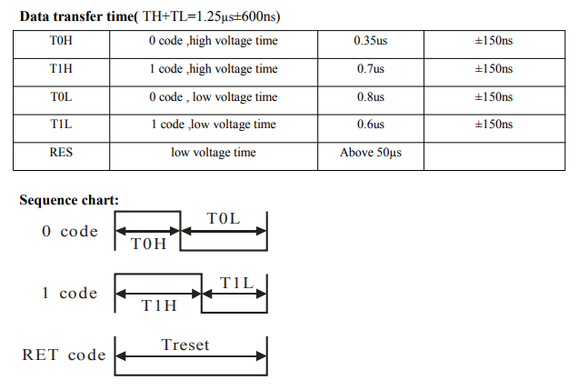
When I disconnected power to the microcontroller, the serial data level dropped to zero, which the WS2812 controllers interpret as a RESET.
It makes sense, but if it’s in the datasheet, I didn’t absorb it on my first read through. The RESET doesn’t just terminate the data stream–the LED’s won’t act on the input until they get the RESET. They were sitting there the whole time with that stream of spammed 1’s in memory, but didn’t actually turn on until they received that terminating segment.
Which means that the raw PWM signal can actually give us a super-hacky way to blink the entire light bar, if we make a loop as follows:
- Set PWM to 67% (spam 1’s)
- Set PWM to 0 (RESET, lights turn on)
- Set PWM to 33% (spam 0’s)
- Set PWM to 0 (RESET, lights turn off)
Firmware code is here, and here it is in action. As you can see, it outputs a ton of light.
The microcontroller can light up the LED’s! It’s not really proper control of the component, since we can’t do colors and we aren’t individually controlling them, just blasting data to the whole array. But it proves out that the PWM signal is the right frequency and the right duty cycles. It also proves that the physical connections and power supply are reasonable, so I’ll take it. Varying the duty cycle for proper control is up next.