PWM Control
So at this point I can write basic programs for the STM32 and get basic serial comms running between the MCU and my machine. It’s time to start thinking about how to actually control the displays.
I got this Neopixel stick from Sparkfun, which I realized when I went hunting for the datasheet is a resell of this Adafruit product. Sparkfun says that this is board contains WS2812 LED’s, while Adafruit says they’ve used SK6812’s on everything they’ve built since 2016, but the protocol is the same. Reading the datasheets, that isn’t quite true; there seem to be some minor timing differences. It’s all pretty close, though, such that a good implementation for one should handle the other just by changing constants.
Controlling the WS2812
Having done a bit of background reading, driving these LED’s from an STM32 is an incredibly well-explored problem on the web, and Adafruit themselves offer a great general guide that isn’t STM32-specific but should still be your first stop. That said, here’s my process and notes.
These lights accept one line of serial control data with a pin for data in and another for data out. Each light will swallow the first 24 bits as its own control frame and then pass the rest of the data through unmodified, so you can control an arbitrary number of lights by chaining one’s DOUT pin to the next one’s DIN. You terminate the sequence with a reset period of low voltage.
A control frame for the WS2812 looks like this:
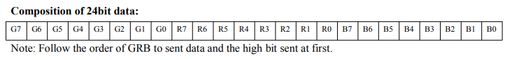
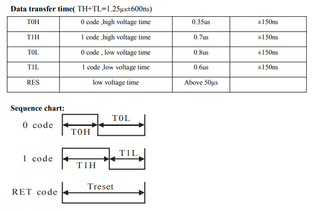
So one byte each for green, red, and blue, in that order, MSB first. What does a bit look like? Here’s the timing specification:
Complete datasheet for the WS2812 if you’d like to deep-dive.
So the total transmission time for one bit should be 1.25μs, consisting of a TH period and a TL period. To send a 1, hold voltage high for T1H (.7μs) then low for T1L (.6μs). Likewise for 0, hold high for T0H (.35μs) then low for T0L (.8μs).
Writing that down, I now realize that, if we take the data sheet at its word, the total time for a 1 isn’t 1.25, and the total time for a zero also isn’t 1.25, AND the time for a 1 doesn’t equal the time for a 0, so… clearly there will be some experimentation.
Stated more simply: to control the LED’s, I need to generate a signal with a fixed period of 1.25μs but variable duty cycle. To send a 0, hold voltage high for a short part of the cycle and low for a longer part. To send a 1, hold voltage high for a longer part and 0 for a shorter part. It’s a good job for the PWM hardware on the STM32.
Configuring the PWM
It’s not clear which LED’s I have, so I’m going to pick something arbitrary and say that a 1 will be a 67% duty cycle and a 0 will be 33%. Once I’m outputting the sort of signals I want, I can fine-tune the timings.
On this platform, PWM generation works as follows:
- Configure one of the built-in timers to count from zero to some maximum value at the desired interval. This interval will be the period of your PWM signal, so we have to set it to the 1.25μs our LED’s expect.
- Configure the duty cycle for that PWM by setting the capture-compare register to represent the timer value where the output goes from high to low.
Configuring the timers from scratch is moderately complicated for a neophyte like me; for a great intro to the topic, have a look at this video tutorial by Shawn Hymel for Digikey. I also relied heavily on this detailed lab on configuring PWM on STM32 by Khaled Magdy.
On the chip that I’m using, there are lots of timers, but three are listed in the data sheet as “general-purpose”: TIM2, TIM15, and TIM16. TIM2 is 32-bit with a 32-bit prescaler, and TIM15 and TIM16 are 16-bit with 16-bit prescalers. I’ve been using TIM16 to blink the onboard LED as a heartbeat. TIM15 would be adequate for our purposes, but its PWM output pin is consumed by the USART for the virtual COM port on the Nucleo. TIM2 it is.
On this chip, TIM2 is driven by the APB2 timer clocks, which are connected to HCLK via the APB2 prescaler. The default HCLK is 32 MHz, so that’s the default max frequency of TIM2.
Recall we need to send bits at 1.25μs = 800 kHz. If we take 32 MHz / 800 kHz, we see there would be 40 ticks of TIM2 per bit of LED control data. Since the whole bit represents 100% of the duty cycle, with 40 ticks of granularity, each tick represents 100% / 40 = 2.5%, so we could set 0%, 2.5%, 5%, 7.5%, etc. Realistically, this is probably adequate, but I was curious to know if I could get 100 ticks per cycle so I could set integer percentages.
Setting up Clocks
That brings me to the Clock Configuration view of STM32CubeIDE:
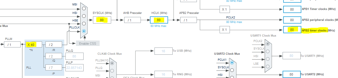
Here, you can manipulate multiplier, mux, and prescaler settings on a graphical view of how everything is connected. It becomes straightforward to see that, as highlighted in this example, increasing the PLLN multiplier from the default of 16 to 40 yields a SYSCLK of 80 MHz. Keeping all the prescalers at 1 yields an APB2 timer clock–and therefore TIM2 max frequency–of 80 MHz.
Note that this affects the base frequency of several timers, not just TIM2. I needed to make some adjustments to my config on TIM16 in order to keep my heartbeat LED blinking at 1 Hz.
Nearly there. Our input frequency is correct, so on to actually configuring TIM2 properly. In the config tool, we set up TIM2 to run at full speed (Prescaler = 0) and runs 100 ticks before cycling over (Counter Period = 99). These registers are zero-based, so expressing the value as “1 - 1” or “100 - 1” lets me write the intended value in human-readable format.
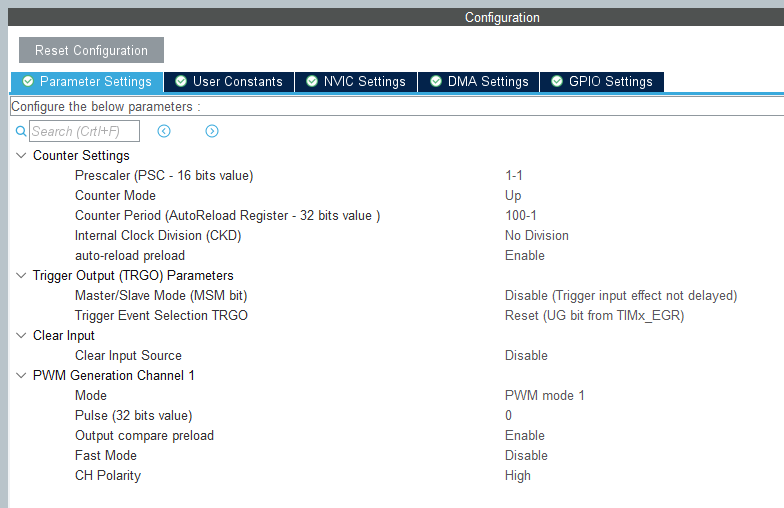
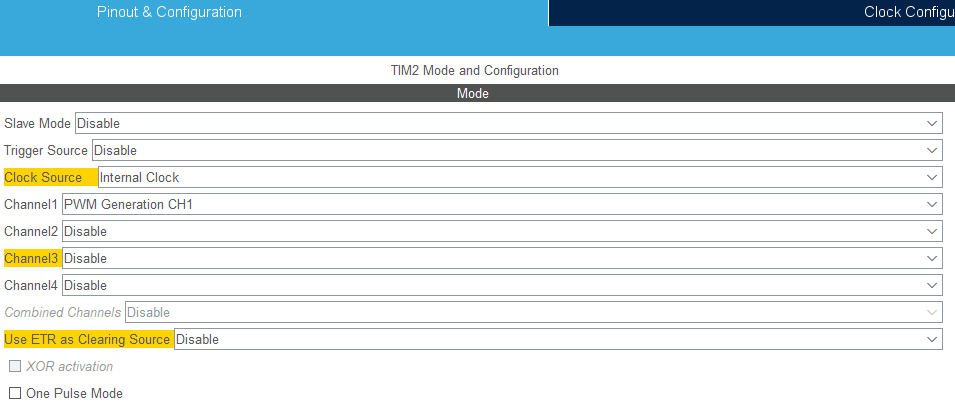
With the timer now cycling at the proper frequency of 800 kHz, we can set up channel 1 of TIM2 to output a PWM signal:
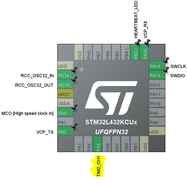
And the chip configurator now shows TIM2_CH1 enabled on PA5:
Controlling the Signal
The very last piece is controlling the duty cycle–for what percentage of the time per cycle is the output voltage high? On an STM32, this is done via the capture-compare register. In the default mode, if the timer’s value is less than the CCR value, the signal is high; otherwise it’s low.
Since we set up our timer to have 100 ticks per cycle, we can tell the signal to be on half the time with
TIM2->CCR1 = 50;
Or on for 67% of the time with
TIM2->CCR1 = 67;
The real power, of course, being that the value of CCR can change to vary the signal, so with a simple loop to toggle it between 33% and 67%, we get:
Measuring the output in the scope, we have a reliable period of 1.25μs and a controllable duty cycle–the foundation of a valid control signal for our LED’s. Source code is checked in here. Next up, I’ll get the Neopixel stick wired to the circuit and display some colors.